 Agrandir l'image
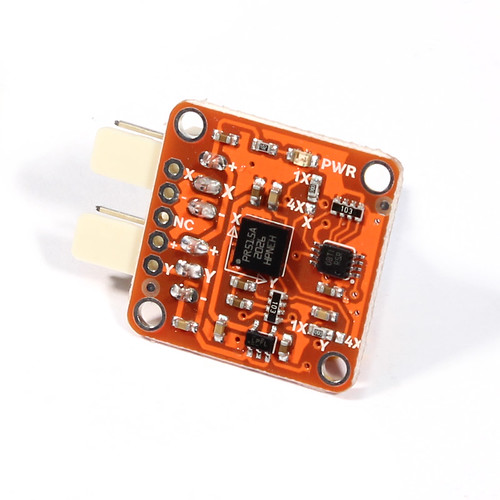
Module TinkerKit Gyroscope 2 axes
T000060
Nouveau produit
Module Tinkerkit d'Arduino avec un gyroscope à 2 axes afin de mesurer l'orientation.
En achetant ce produit vous pouvez gagner jusqu'à 2 points de fidélité. Votre panier totalisera 2 points pouvant être transformé(s) en un bon de réduction de 1,00 €.

En savoir plus
Module TinkerKit Gyroscope 2 axes
Introduction
Un gyroscope est un système qui permet de mesurer l'orientation. Il est très utiliser dans les appareils électroniques que les appareils portable et les manettes de jeux vidéo pour détecter le mouvement et l'orientation.
Sortie: Le module délivre du 0v à 5V sur les des pins lorsque l'angle change (c.a.d il bouge). la valeur est à peu prés du 2.5V lorsqu'il n'y a pas d'angle avec l'axe X ou Y. Lorsque le module est connecté à une entrée de l'Arduino par l'intermédiaire de la carte d'extension Tinkerkit, vous pouvez vous attendre à récupérer une valeur entre 0 et 1023 en fonction de l'angle du module.
Description du module
sur la carte, vous pouvez trouver une LED verte indiquant l'alimentation correcte du module. Ce module est basé sur le composant LPR5150AL de la société ST Microelectronics qui est gyroscope 2 axes. Cette version du module renvoie les pins 1X du composant. Pour plus de détails, veuillez consulter la doc technique du composant.
Ce module est un CAPTEUR. Le connecteur est une SORTIE (OUTPUT) qui doit être branché à un connecteur d'ENTREE (INPUT) de la TinkerKit Shield.
NB: Le module est livré sans câble.
Code d'Exemple
/* TinkerKit! Gyroscope [T000060-64]
*
* This sketch shows how to read this 2-axis gyroscope,
* turning in a given angular velocity and then converting it
* in the simplest way in an angular position (/inclination).
*
* Connect: the X-axis to the Analog Input Pin 0 (I0)
* the Y-axis to the Analog Input Pin 1 (I1)
* Optional: connect a servo to Analog Output Pin 9 (O2)
*
* created by Federico Vanzati / f.vanzati@arduino.cc
* in September 2011
*
* inspired from www.arduino.cc/playground/Main/Gyro
* by eric barch / ericbarch.com
*/
#include <Servo.h>
// Pin used in this example
#define SERVO 9
#define X_GYRO 0
#define Y_GYRO 1
#define ADCresolution 4.89f // = 5000mV/1023counts: Arduino analog pins resolution expressed in mV/count
#define Sensitivity 0.67f // [mV/dps] sensitivity of the sensor, took from datasheet (4x output mode)
// Conversion coefficient, we do here because is a constant! so we'll not do the calculation every loop
#define K ADCresolution/Sensitivity // the constant!
#define nrSamples 6 // Number of samples that we take for each measure
Servo myservo; // create servo object to control a servo
// a maximum of eight servo objects can be created
// Timing variables
unsigned long time, sampleTime = 12;
unsigned long printTime = 0, serialRefresh_time = 500;
float deltaT = (float)sampleTime*nrSamples/1000;
//Gyroscope variables
int roll_zeroVoltage, pitch_zeroVoltage;
int roll_rawADC[nrSamples], pitch_rawADC[nrSamples]; // store 3 values...just to avverage
float roll_rate, pitch_rate; //
float roll_angle = 0, pitch_angle = 0;
int c=0; // just a counter to count the samples
int pos; // variable to store the servo position
void setup()
{
delay(1000);
myservo.attach(SERVO); // attaches the servo on pin 9 to the servo object
myservo.write(pos);
Serial.begin(57600);
Serial.print("TinkerKit! Gyroscope [T000062] Test Examplenn");
int correctionY=0, correctionX=0;
for (int i=0; i<50; i++)
{
correctionY += analogRead(Y_GYRO);
correctionX += analogRead(X_GYRO);
delay(20);
}
roll_zeroVoltage = correctionY/50;
pitch_zeroVoltage = correctionX/50;
Serial.print(roll_zeroVoltage);
Serial.print(" ");
Serial.println(pitch_zeroVoltage);
time = millis();
}
void loop()
{
// Every 40ms take a sample from gyro
if(millis() - time > sampleTime)
{
time = millis();
roll_rawADC[c] = analogRead(Y_GYRO);
pitch_rawADC[c] = analogRead(X_GYRO);
c++;
}
if(c==nrSamples) // Well, we have 3 samples
{
// Transform the raw data into an angular velocity
roll_rate = (filterGyro(roll_rawADC) - roll_zeroVoltage) * K;
pitch_rate = (filterGyro(pitch_rawADC) - pitch_zeroVoltage)* K;
// Integrate the angular veloity to obtain angular position (or inclination)
// Using the trapeziod method for numerical integration
// sampleTime*nrSamples
// The variable that take mind of the integration time is deltaT = --------------------
// 1000
// - we multiply for nrSamples because
// - divide for 1000 because angular velocity is expessed in seconds,
// but sampleTime is expressed in milliseconds
roll_angle += roll_rate*deltaT/2;
pitch_angle += pitch_rate*deltaT/2;
//Keep our angle between 0-359 degrees
if (roll_angle < 0)
roll_angle += 360;
else if (roll_angle > 359)
roll_angle -= 360;
if (pitch_angle < 0)
pitch_angle += 360;
else if (pitch_angle > 359)
pitch_angle -= 360;
// Now we control the servo: home position is setted in the center at 90 degrees
if(roll_angle >= 0 && roll_angle <= 90) // counterclockwise rotation of the gyro...
pos = 90 + (int)roll_angle; // ...produces rotation from 90 to 180 deg on servo
if(roll_angle >= 270) // clockwike rotation of the gyro...
pos = (int)roll_angle - 270; // ...produces rotation from 90 to 0 deg on servo
myservo.write(pos); // send the position to servo
if(millis() - printTime > serialRefresh_time)
{
printTime = millis();
Serial.print("Roll speed: "); Serial.print((int)roll_rate);
Serial.print("t Angle: "); Serial.print((int)roll_angle);
Serial.print("t Pitch speed: "); Serial.print((int)pitch_rate);
Serial.print("t Angle: "); Serial.println((int)pitch_angle);
Serial.print("Servo: "); Serial.println(pos);
}
c=0; // reset the counter
}
}
int filterGyro(int buffer[])
{
int mean=0;
for(byte i=0; i<nrSamples; i++)
mean += buffer[i];
mean /= nrSamples;
return mean;
}
Avis
Aucun avis n'a été publié pour le moment.
Accessoires