Module TinkerKit LDR: capteur de lumière
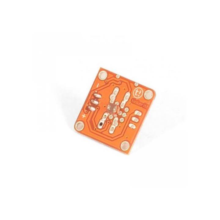
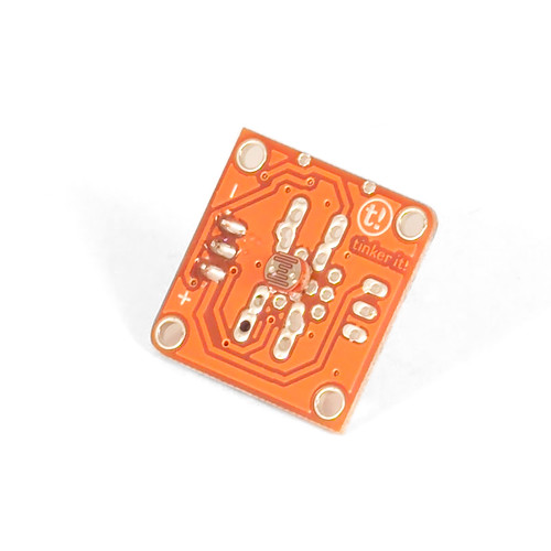
Module Tinkerkit d'Arduino avec une photorésistance pour capter la lumière (LDR).
Introduction à la photorésistance ou LDR
la photorésistance, en anglais LDR (Light Dependant Resistor) est une résistance variable. Lorse que la lumière reçue par le capteur décroit, la valeur de la résistance diminue.
Sortie: Ce module fournit un tension de 5V lorsqu'il ne reçoit aucune lumière (le circuit est ouvert) et 0V lorsqu'il reçoit une lumière importante. Presser le bouton ferme le circuit. Lorsque le module est connecté à une entrée de l'Arduino par l'intermédiaire de la carte d'extension Tinkerkit, vous pouvez vous attendre à récupérer une valeur entre 0 et 1023.
Description du Module Tinkerkit LDR pour Arduino
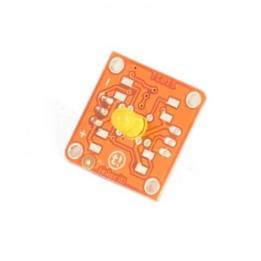
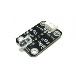
Ce module comprend une photorésistance, un amplificateur de signal,un connecteur TinkerKit 3 pins standard, une LED verte signalant que le module est correctement alimenté et une LED jaune plus ou moins brillante en fonction de la quantité de lumière détectée.
Ce module est un CAPTEUR. Le connecteur est une SORTIE (OUTPUT) qui doit être branché à un connecteur d'ENTREE (INPUT) de la TinkerKit Shield.
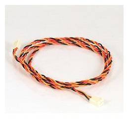
NB: Le module est livré sans câble.
Exemple de Code
Analog input, analog output, serial output
Reads an analog input pin, and T000090 LDR Analog Sensor connected to I0, maps the result to a range from 0 to 255
and uses the result to set the pulsewidth modulation (PWM) on a T010111 LED Module connected on O0.
Also prints the results to the serial monitor.
created 29 Dec. 2008
Modified 4 Sep 2010
by Tom Igoe
modified 7 dec 2010
by Davide Gomba
This example code is in the public domain.
*/
#define O0 11
#define O1 10
#define O2 9
#define O3 6
#define O4 5
#define O5 3
#define I0 A0
#define I1 A1
#define I2 A2
#define I3 A3
#define I4 A4
#define I5 A5
// These constants won't change. They're used to give names
// to the pins used:
const int analogInPin = I0; // Analog input pin that the LDR is attached to
const int analogOutPin= O0; // Analog output pin that the LED is attached to
int sensorValue = 0; // value read from the pot
int outputValue = 0; // value output to the PWM (analog out)
void setup() {
// initialize serial communications at 9600 bps:
Serial.begin(9600);
}
void loop() {
// read the analog in value:
sensorValue = analogRead(analogInPin);
// map it to the range of the analog out:
outputValue = map(sensorValue, 0, 1023, 0, 255);
// change the analog out value:
analogWrite(analogOutPin, outputValue);
// print the results to the serial monitor:
Serial.print("sensor = " );
Serial.print(sensorValue);
Serial.print("t output = ");
Serial.println(outputValue);
// wait 10 milliseconds before the next loop
// for the analog-to-digital converter to settle
// after the last reading:
delay(10);
}
(edit with the Customer Reassurance module)